In practice usually the tuners have directly the head to be worked and not
have available the three-dimensional drawings of intake and exhaust ducts
to study them through CFD simulations, for this the software
Head Design was designed to recreate the main geometry
main of the
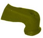
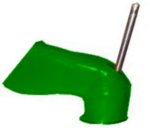
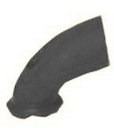
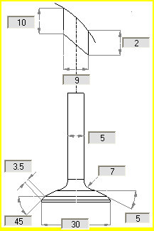
duct through simple workshop measurements , which can
be made directly on the head, or creating the mold of the
duct and measuring it.
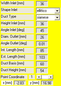
Thanks to simple measures it is possible
to insert
easily in the software the geometric characteristics of the section
main of the duct, of the valve guide and of the
valve.
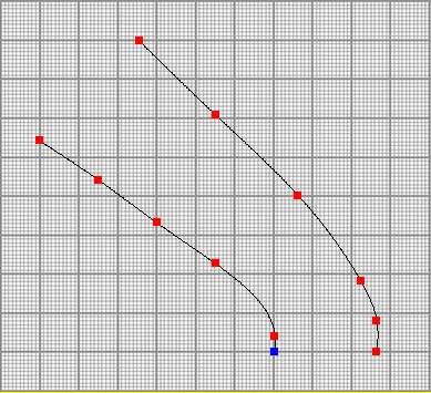
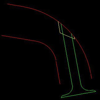
For what concerns the geometry of the main section
of the
head ducts in the software there is a millimeter area with
two spline curves that allow to define the shape of the
internal and external profiles of the duct simply
dragging control points and seeing in real time
how to edit the curve. The coordinates of the points of
control can also be entered manually, then
measuring, the mold of the duct, or some key dimensions
of the duct in the engine head, you can easily recreate the
geometry to study and optimize with the software. |
 |
 |
 |
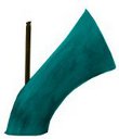
After entering the required data, you can see the
geometry that has been recreated for the duct, the guide
valve and valve.
This geometry is aimed at identifying the main geometries characteristics
of the duct in terms of lengths,
curvatures and impediments, in order to make a
calculation on the fluid-dynamic basis of the main factors that
determine the losses during the flow passage
through the duct. |
 |
After displaying the inserted geometry, you can proceed to the
calculation. The software performs a flowbench simulation of the
duct and determines, through appropriate fluid dynamics calculations,
the losses that will occur through the duct at the passage of the
flow.
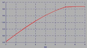
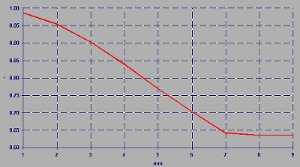
At the end of the calculation the software shows as a function of the lift
valve the following quantities:
| TOTAL DISCHARGE COEFFICIENT |
| FLUID DYNAMIC DISCHARGE COEFFICIENT |
| FLOW RATE |
| GEOMETRIC AREA |
| EFFECTIVE AREA |
| AVERAGE GEOMETRIC AREA |
| AVERAGE EFFECTIVE AREA |
Thanks to the calculated quantities you can have a
clear picture of the characteristics of the duct, both in terms of
passage areas, both for what concerns pressure
and flowrate losses that will occur for the flow.
These results will be the reference to study
through the software the geometric changes that
allow you to optimize the duct to reduce fluid dynamics losses and increase the flowrate at all advantage
of the engine performance. |
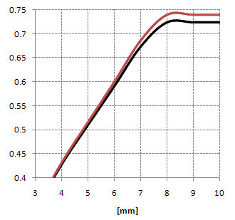
| TOTAL DISCHARGE COEFFICIENT |
 |
| FLUID DYNAMIC DISCHARGE COEFFICIENT |
 |
|
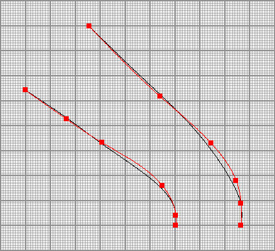
In fact, after the calculation on the initial geometry will be possible to simulate the geometric changes that
you intend to make on the duct and verify if they will be improving or
less. This will allow you to find the correct direction first
to proceed with the realization , thus avoiding many
practical attempts before to reach the desired solution.
This phase in the software is very simple, in fact in a specific zone is shown a millimeter area, with drawn the
initial geometry in black, which can be easily changed
simply by moving the points of control and seeing in red the
new geometry.
 |
After entering the
changes to be made on the duct will be sufficient
perform the calculation to see if the interventions hypothesized
actually bring improvements.
Based on the results it will be easy to understand the direction
of the interventions to be carried out, and then working with the software
will be possible to identify the changes that allow
to optimize the geometry. |
| TOTAL DISCHARGE COEFFICIENT |
FLUID DYNAMIC DISCHARGE COEFFICIENT |
 |
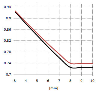 |
|
The software Head Design is therefore a tool for all those who
they can not use CFD simulation, but that want to
equally have a help from the calculation to optimize at the best the engine head.
In fact, although the software works on a simplified geometry
characterizing the duct, it is able to seize the
main effects of the changes that you want to make and then
orientate the development in the best direction.
|